 Bioliff
Water . Tech
Free
Bioliff SBR wastewater treatment plants use the Sequential Batch Reactor process to provide effective treatment of sewage water in various applications in scale from residential to large communities. The SBR process provides for full Carbon and Nitrogen removal and produces high quality effluent that is odour free and suitable for re-use including irrigation and toilet flushing. Due to its high quality it may also be discharged into sensitive water courses.
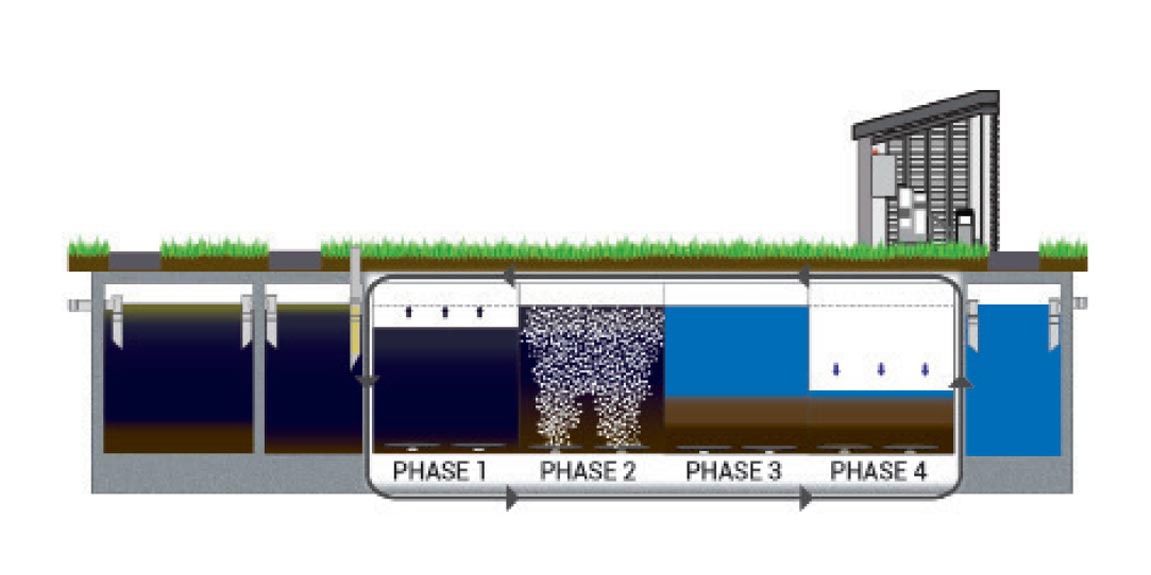
SBR systems use in-ground site constructed concrete chambers with ancillary equipment including aerators and pumps centrally installed and controlled in an adjacent machinery housing room. The purification process includes:-
Primary Treatment: Raw sewage and grey water is first processed in a two stage Primary Treatment chamber where liquids and solids are separated and some sedimentation takes place. The resultant settled fluid is then pumped to the main reactor tank in a batch of about 25% of daily treatment load.
Secondary Treatment: Secondary treatment occurs in a four phase process that includes aeration, biodegradrading and settlement, sludge settling to the bottom of the chamber while clarified water rises to the surface. This process takes about six hours after which the treated water is transferred to the final stage chamber and a new batch of raw water is introduced.
Storage: Chlorine dosage is introduced in the storage chamber after which the water is either utilised for irrigation, wash down etc or safely discharged to waste.
A feature of the design is an intelligent programmable controller that monitors chamber water level and controls the batch pumping and aeration without float switch control. Other functionalities including level alarms and plant malfunction are also included.
Reliable Pedrollo submersible sewage pumps are used for water transfer between cycles and aeration is provided by separate blower unit.
Bioliff SBR plants are of modular design and are specified according to particular population size, treatment requirements and site conditions, full details being provided for each installation.
*The design and layout is very flexible. For alternative layouts, smaller foot prints, or different depths please enquire.
**Due to the intelligent control panel and SBR cycle process the actual power consumption is much lower than the installed power would suggest e.g. 8PE SBR = estimate of less than 400kWh/year!
SBR systems use in-ground site constructed concrete chambers with ancillary equipment including aerators and pumps centrally installed and controlled in an adjacent machinery housing room. The purification process includes:-
Primary Treatment: Raw sewage and grey water is first processed in a two stage Primary Treatment chamber where liquids and solids are separated and some sedimentation takes place. The resultant settled fluid is then pumped to the main reactor tank in a batch of about 25% of daily treatment load.
Secondary Treatment: Secondary treatment occurs in a four phase process that includes aeration, biodegradrading and settlement, sludge settling to the bottom of the chamber while clarified water rises to the surface. This process takes about six hours after which the treated water is transferred to the final stage chamber and a new batch of raw water is introduced.
Storage: Chlorine dosage is introduced in the storage chamber after which the water is either utilised for irrigation, wash down etc or safely discharged to waste.
A feature of the design is an intelligent programmable controller that monitors chamber water level and controls the batch pumping and aeration without float switch control. Other functionalities including level alarms and plant malfunction are also included.
Reliable Pedrollo submersible sewage pumps are used for water transfer between cycles and aeration is provided by separate blower unit.
Bioliff SBR plants are of modular design and are specified according to particular population size, treatment requirements and site conditions, full details being provided for each installation.
| Model | 10PE | 20PE | 30PE | 50PE | 75PE | 100PE | 150PE | 200PE | 300PE | 500PE | 750PE |
| Population Equivalent (PE) | 10 | 20 | 30 | 50 | 75 | 100 | 150 | 200 | 300 | 500 | 750 |
| Flow (m3/day) | 1.5 | 3 | 4.5 | 7.5 | 12 | 15 | 23 | 30 | 45 | 75 | 112 |
| Organic Loading (kg/BOD/day) | 0.6 | 1.2 | 1.8 | 3 | 4.5 | 6 | 9 | 12 | 18 | 30 | 45 |
| Nitrogen Loading (kg/NH/day) | 0.08 | 0.16 | 0.24 | 0.4 | 0.6 | 0.8 | 1.2 | 1.6 | 2.4 | 4 | 6 |
| Length (m) | 2.0 | 3.9 | 4.5 | 6 | 6 | 6.5 | 8 | 7.5 | 14 | 10 | 13 |
| Width (m) | 1.8 | 2.6 | 3 | 4 | 3.5 | 4 | 5 | 4.7 | 3.7 | 7 | 7.5 |
| Depth (m) | 1.5 | 2 | 2 | 2.2 | 2 | 2 | 2 | 3.5 | 3.5 | 3.5 | 3.5 |
| Foot Print (m2) | 1.7 | 10 | 14 | 24 | 21 | 26 | 40 | 35 | 52 | 70 | 98 |
| Total Tank Volume (m3) | 5 | 20 | 27 | 53 | 42 | 52 | 80 | 123 | 181 | 245 | 341 |
| Installed Power (kWh/month) | 0.59 | 0.77 | 21 | 2.6 | 3.02 | 7.5 | |||||
*The design and layout is very flexible. For alternative layouts, smaller foot prints, or different depths please enquire.
**Due to the intelligent control panel and SBR cycle process the actual power consumption is much lower than the installed power would suggest e.g. 8PE SBR = estimate of less than 400kWh/year!

